by Melissa Donovan
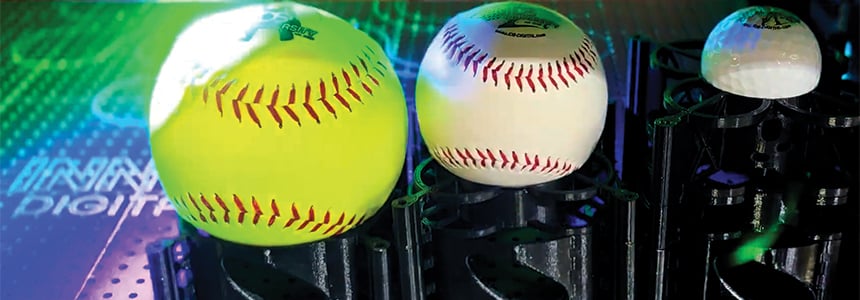
Direct to object (DTO) printers evolve to print directly to any number of shapes, objects, and sizes. One consideration as the range of printed products grows is the gap between printhead and object.
Above: The Mutoh XpertJet 661UF prints directly on to a variety of substrates up to 5.91 inches thick, like plastic blocks.
“The demand for printing DTO on dimensional, curved, and complex shapes has made larger print gaps essential—not optional. High-gap printing expands what manufacturers can decorate, allowing larger graphics, greater coverage, and new applications,” attests Michael Perrelli, director of sales, Innovative Digital Systems (IDS).
Today’s print technology—printhead, ink, software—makes this possible by maintaining print performance even at these wider distances.
Average Distance
The average distance between the printhead and object is changing, especially as applications are introduced that drive the need for larger print gaps to avoid collisions.
“There is a higher expectation to have clear prints on products with more curved surfaces, textures, recessed area, and just generally uneven surfaces. Part of this includes expanding the ability to print clearly with a higher printhead gap and at variable distance,” explains Hugo Gonzalez, senior segment specialist, Mimaki USA, Inc.
Neil Cook, head of strategic marketing, Xaar, says there is a clear shift from gaps below two millimeters (mm) toward three to even ten mm in some industrial applications. “This is driven by coding and marking on corrugated and secondary packaging, direct to shape printing, high-speed packaging lines, and production environments where dust, vibration, and contamination risk need to be managed.”
Kenneth Stack, executive chairman, Engineered Printing Solutions, notices the same shift in print gap size, from two to ten mm, depending on the application. “Print gap is critical because many objects are not perfectly flat or dimensionally stable. This is true for round items such as cans or balls, as well as molded components like plastic lids, which can warp.”
Based on Koenig & Bauer Kammann (US) Inc.’s experience, a common question from customers is “how do we decorate more surface area on containers that aren’t flat?” A good example is the specialty brewery glass market. “A traditional pint glass is straight forward, but a Belgian tulip or a glass with a pronounced foot and bulbous body creates real challenges. Decorators want full coverage on those curves, and that demand is pushing the conversation on throw distance further than ever,” continues Nevin White, sales manager, Koenig & Bauer Kammann.
Practicality in Action
There are limits to how far a printhead can be positioned from an object, based on the printer and object in question.
“In any DTO application there is a theoretical maximum to the distance a system can project ink effectively onto a surface. The actual capabilities of the printhead, combined with the viscosity and drop configurations of the ink, and the system alignment all work together. The reality is, optimal print clarity will be achieved when the correct distance from the printhead is used and the system is aligned to that distance,” says Lon Riley, founder/CEO, DPI Laboratory.
Three things contribute to this, according to Paul Edwards, VP of the digital division, INX International Ink Co. “First, the drop speed must be high enough to ensure it reaches the substrate. Secondly, the drop accuracy of the printheads will limit the throw as the distance increases. If the nozzles have a high level of angular deviation, the drops will not hit the target spot accurately, which leads to print quality issues. Lastly, the amount of mist increases with throw distance. Mist can impact printhead reliability and find its way all over the printer.”
Mike Pruitt, product manager, Professional Imaging, Epson America Inc., notes that “as the printhead gap increases, droplet trajectories deviate, droplets decelerate, and airflow can disrupt droplet placement, resulting in blur, graininess, dot gain, and reduced edge sharpness.”
“At its lowest sizes, environmental factors such as humidity, static, air movement, and temperature influence how the droplet travels. The farther the droplet has to travel before reaching the surface, the more time those factors have to affect placement and as a result the quality of the print. That is why longer printhead gaps require more than simply raising the printhead. The printer, ink, waveform, print profile, and application all need to work together,” adds Gonzalez.
Gregory Harwood, director of digital product management and global service, Inkcups, also stresses that “achieving longer throw distances requires careful optimization of the entire printing system to ensure image quality remains consistent.”
“It is wholly dependent on what machinery you are printing with, the printhead being utilized, the ink jetted, and the software driving the print electronics. Those elements have to be working in tandem. Then the proper use of settings to tune your machine is what maximizes your print gap and establishes those limits,” adds Perrelli.
White admits that “physics set the ceiling. Beyond a certain distance, droplet integrity breaks down regardless of the quality of your ink and hardware.”
“At some point, physics takes over. The bigger challenge today isn’t usually the overall object height—its the variation between the highest and lowest points of the object. A tumbler with a slight taper or a product with contours can be more challenging than a tall flat object. The good news is that improvements in dot placement and carriage control have helped printers maintain quality over larger height variations than ever before,” continues Emilio Rangel, product manager, Mutoh America, Inc.
Operator Setup
Larger print gaps influence operator setup procedures.
For most operators, setup is easier than it was a few years ago. “A lot of the manual adjustments have been replaced by automation. Users can save preferred print gap settings and quickly recall them when running repeat jobs. Once a shop establishes a workflow for a particular product, setup becomes very straightforward,” notes Rangel.
Cook argues that “larger print gaps can make systems less sensitive to tight mechanical tolerances, which helps simplify setup and print integration into high-speed production lines.”
“One of the key benefits of larger print gap capabilities is actually the reduction in setup complexity. With conventional systems, operators often need to spend considerable time ensuring products are positioned within tight tolerances to avoid challenges like printhead strikes and image quality issues. By allowing greater tolerance for height variation, larger print gaps can simplify setup and reduce the frequency of adjustments,” agrees Hardwood.
In an ideal situation, print gap adjustment is handled automatically by the system. “In higher end, single-pass platforms, cameras and servo-driven mechanisms are often used to dynamically adjust printhead position. In contrast, lower cost multi-pass systems rely more on manual setup and adjustment. The level of automation largely depends on the production volume, application complexity, and system design,” shares Stack.
Sensing Technologies
Sensing technologies can detect object height automatically. Laser sensors and camera-based systems are popular.
Most modern systems have automatic height sensing. This provides a predictably safe gap from the object to the printhead for normal operation. Laser break beam systems are still the most prevalent in the smaller and medium format machines, notes Riley.
Laser-based sensing systems are the most commonly used technology for automatic object height detection, as they provide an excellent balance of accuracy, reliability, and cost, admits Pruitt.
“Camera-based vision systems are more prevalent, and this technology has improved since it was first introduced. This allows for enhanced ‘repeatability’ of the prints and can significantly reduce setup times, with increased scanning speeds making more frequent changeovers far more viable,” explains Harwood.
Vision systems and artificial intelligence (AI) also play a role in the process.
“Vision systems are now widely deployed in single-pass production environments, not only for positioning but also for real-time quality control,” adds Stack.
Perrelli believes that “as the demand for decorating more dimensional products grows, decorators will need systems with greater flexibility and built-in features like laser sensing, machine vision, and automated height detection to drive setup automation, part recognition, and print optimization.”
Combining vision systems with machine learning will make it easier to automatically identify defects that negatively impact print quality. “The end result is a system that is more easily optimized for print quality and reliability,” says Edwards.
White sees vision systems with AI-assisted detection becoming more popular. “This is particularly where container geometry varies significantly or changeovers are frequent. For high-mix production environments, the case for smarter sensing gets stronger.”
Visual Appearance
Print gap influences image sharpness, color consistency, and registration.
“As the print gap increases, print quality and perceived resolution can decrease. The greater the distance between the printhead and substrate, the more opportunity for droplets to deviate from their intended path, reducing placement accuracy. This can result in softer detail, less-defined edges, and an overall reduction in image quality,” notes Pruitt.
As in most cases “the correct balance depends on the application and the production conditions. In coding and marking, for example, the priority is usually code readability and robustness rather than photographic resolution. For more graphic or decorative applications, shorter gaps are still generally preferred where possible to ensure the required results,” explains Cook.
Another trade off is speed. “Generic distance—adjusting the ink droplet size and slowing the print carriage to maintain high print quality when printing on challenging objects—does two main things. It alters the ink droplet size to counter the irregular shape of the substrate and it slows the printhead down so the ink droplets fall and cure where they are supposed to,” according to Philip Chu, product manager, Roland DGA.
Mind the Gap
As DTO applications expand beyond flat, uniform surfaces to curved, contoured, uneven, textured, and tiered pieces the ability to maintain print quality across larger printhead gaps is imperative.
Sep2026, Industrial Print Magazine